The creation of detailed system diagrams stands as a cornerstone for architecting efficient and scalable systems. Among the essential tools available to developers, the UML class diagram is as a powerful visual aid that depicts the structural elements, relationships, and functionalities of a software system. Before we start creating a Hospital Management System class diagram with the Gleek app, it's important to understand the basics of UML class diagrams and how they help build strong software systems.
Understanding UML Class Diagrams
A UML (Unified Modeling Language) class diagram is serving as a type of static structure diagram that precisely describes the structure of a system. It achieves this by illustrating the system's classes, detailing their attributes and methods, and delineating the relationships among them. This diagram type is important for developers and engineers, as it provides a clear and comprehensive visualization of the system's architecture. It facilitates a deeper understanding of how different components interact within the system, making it an indispensable part of the planning and design phase in software development. By using UML class diagrams, software professionals can communicate complex system structures and interactions in a universally understood visual format, thereby enhancing collaboration and efficiency in the development process.
Make your own UML class diagram with Gleek.
What is a UML Class Diagram Used For?
Structural visualization: UML class diagrams provide a visual representation of the structure of a system, making it easier to understand the relationships between various classes and their roles within the system. For instance, our step-by-step tutorial on creating a class diagram for a library management system helps you visualize how books, members, and transactions interact within the system.
Communication tool: They serve as a communication tool between developers, designers, and stakeholders, helping to convey complex system structures in a simplified manner. Our guide on restaurant management systems demonstrates how class diagrams can facilitate clear communication about the interactions between customers, orders, and kitchen staff.
Code generation: UML class diagrams can be used to generate code directly from the visual representation, speeding up the development process. The ATM system class diagram tutorial illustrates how these diagrams can streamline code generation by mapping out interactions between accounts, transactions, and user interfaces.
Documentation: They aid in documenting the system architecture, making it easier for future developers to maintain and enhance the system. Our online shopping system tutorial shows how a well-documented class diagram can simplify understanding of the relationships between products, customers, orders, and payments.
By understanding the purpose and benefits of UML class diagrams, you can effectively utilize the Gleek app to create a comprehensive class diagram for a Hospital management system.
Hospital Management System and Its Components
The Hospital Management System comprises various essential components that collectively ensure the seamless operation and delivery of healthcare services. Understanding these components is key for designing an effective class diagram. Let’s dive into each component in detail:
Patient: The Patient component represents individuals seeking medical care within the hospital system. It encompasses personal information, medical history, and treatment records of patients. In the class diagram, this component helps visualize the flow of patient information throughout various hospital services, enhancing data management and accessibility.
Doctor: The Doctor component signifies healthcare professionals responsible for diagnosing illnesses, prescribing treatments, and providing medical care to patients. It includes details such as specialty, qualifications, and schedule. In a class diagram, this helps in planning resource allocation, scheduling, and the integration of various specialties within the hospital ecosystem.
Appointment: The Appointment component refers to scheduled meetings between patients and doctors for medical consultations and treatments. It manages appointment scheduling, reminders, and availability of healthcare providers. This component in the class diagram aids in optimizing patient flow and resource usage, ensuring efficient time management within the hospital.
Hospital: This component denotes the healthcare facility where medical services are provided. It includes departments, wards, administrative offices, and infrastructure details of the hospital. Mapping this out in a class diagram provides a bird's-eye view of the facility’s operational framework, which is vital for strategic planning and administration.
Billing: The Billing component encompasses financial transactions related to healthcare services rendered to patients. It includes billing details, payment processing, insurance claims, and financial reports. In the class diagram, this component is crucial for integrating financial processes with medical services, facilitating streamlined revenue cycle management.
Medical Record: The Medical Record component stores and manages the medical history, diagnoses, prescriptions, and test results of patients. It ensures secure storage and accessibility of patient health information. Representing this in a class diagram helps ensure compliance with medical regulations and improves the security and efficiency of information exchanges within the hospital.
Creating a class diagram for these components not only clarifies the structure and interconnections of the hospital management system but also enhances the understanding and communication among developers, hospital administrators, and other stakeholders. This visualization aids in identifying potential issues, optimizing processes, and scaling operations effectively. Thus, a well-crafted class diagram is indispensable for the development, maintenance, and enhancement of an integrated hospital management system.
Step-by-step guide on how to create a UML class diagram for hospital management system
Start with a new diagram
Open app.gleek.io and click on "New Diagram." Choose "Class diagram" from the list to start fresh.
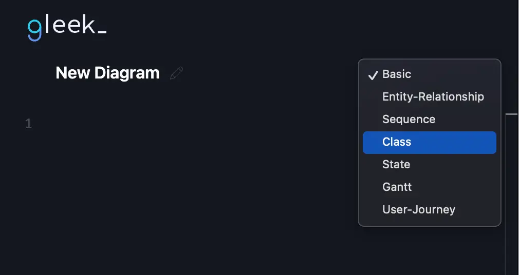
Add the Patient class
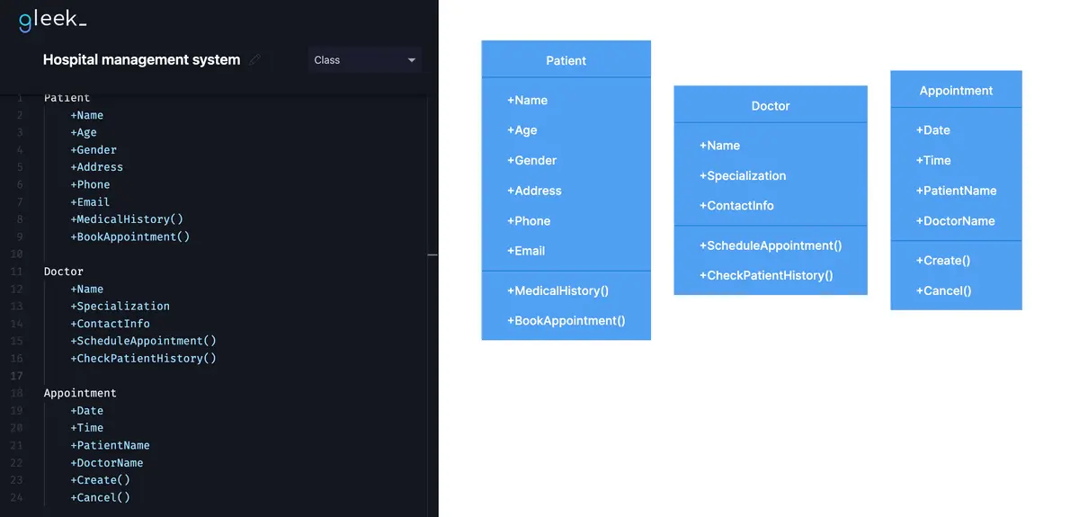
First, we'll add the "Patient" class. Just type "Patient" and it will appear on your chart.
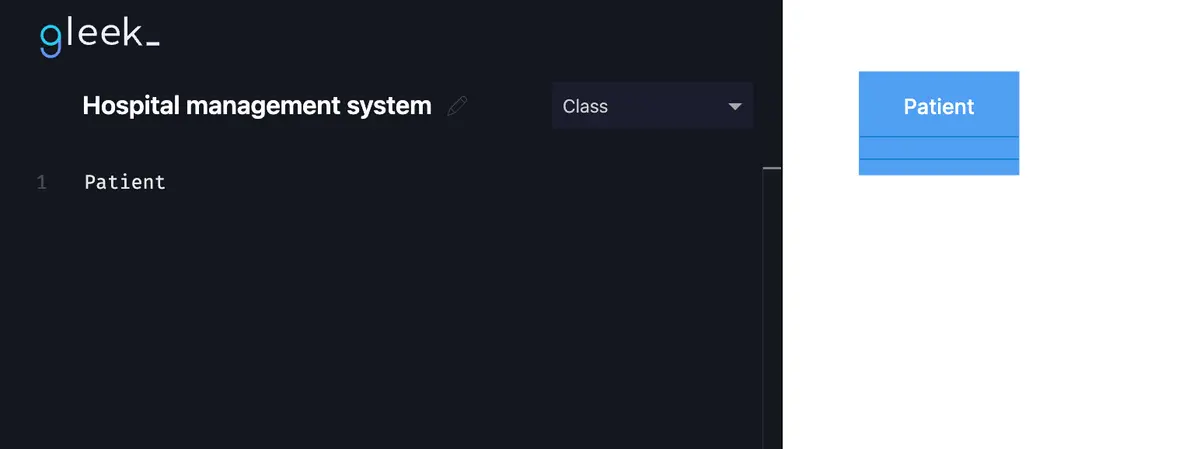
Make your own UML class diagram with Gleek.
Now, to add attributes such as "Name", "Age", "Gender", etc., go to a new line, press "Tab", and write the attribute name. After entering the first attribute, press "Tab" again to continue adding more.
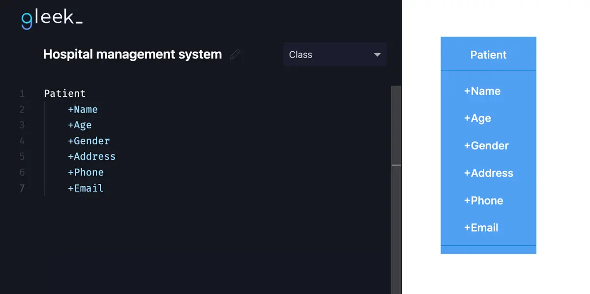
Perfect, and now, let's add methods to the "Patient" class. Press "Tab" on a new line and write method names like "MedicalHistory()" and "BookAppointment()". Do not forget to add "()" at the end of each method.
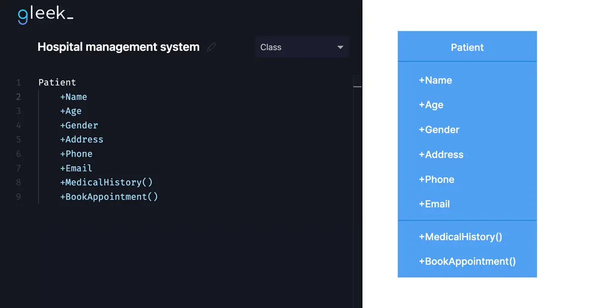
Add the Doctor class
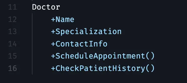
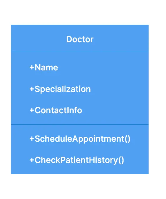
Let's move to the "Doctor" class. Type "Doctor" to create the class. Add attributes like "Name", "Specialization", and "ContactInfo" by following the same tabbing method.
Also, add methods "ScheduleAppointment()" and "CheckPatientHistory()" to handle doctor operations.
Add the Appointment class
Let's move to the "Appointment" class. Type "Appointment" to create the class.

Add attributes like "Date", "Time", "PatientName", and "DoctorName" by following the same tabbing method.
Also, add methods "Create()" and "Cancel()" to handle appointment operations.
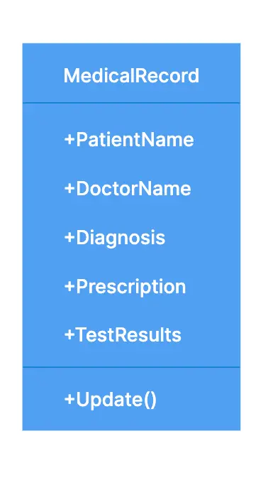
Define the MedicalRecord class
Next, create the "MedicalRecord" class. Type "MedicalRecord", and add attributes such as "PatientName", "DoctorName", "Diagnosis", etc., using the tab method.
Make your own UML class diagram with Gleek.
Include a method called "Update()" to update the records, added in the same way as other methods.
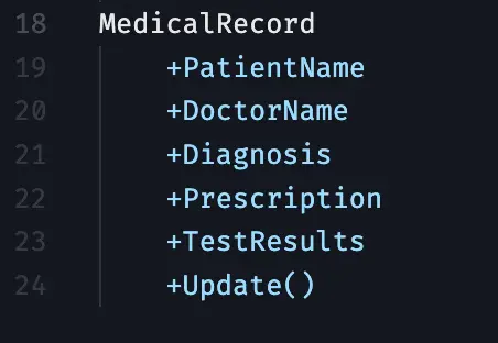
It will look like this in Gleek app:
Include the Billing class
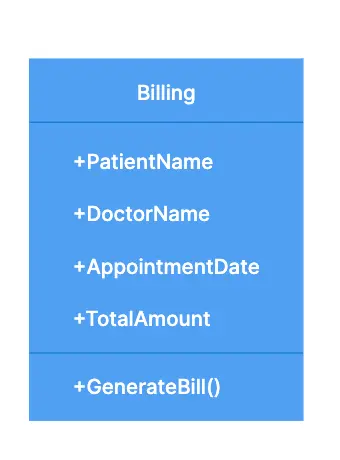
Now, add the "Billing" class by typing "Billing". Input attributes like "PatientName", "DoctorName", "AppointmentDate", and "TotalAmount" using the tab method.
The method "GenerateBill()" should also be added using the tab method, essential for generating bills for services.
Include the Hospital class
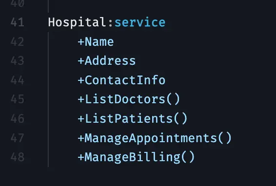
As hospitals are central to the system, type "Hospital" and add attributes like "Name", "Address", "ContactInfo" to represent hospital details.
Define relationships between classes
Establish relationships between classes to depict the interactions within the system:
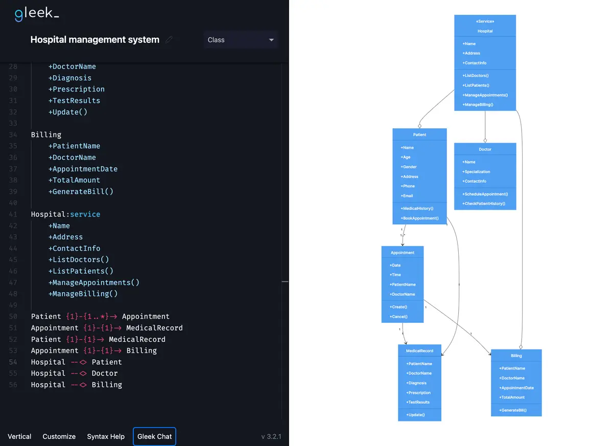
Patient to Appointment: type Patient {1}-{1..*}-> Appointment from the new line. This relationship is called multiplicity and shows that a patient can have multiple appointments. It's essential for tracking all visits a patient makes to the hospital.

Appointment to MedicalRecord: Use Appointment {1}-{1}-> MedicalRecord. Each appointment might involve reviewing or updating a patient's medical record, reflecting real-life interactions where healthcare providers need access to historical health information during patient visits.

Patient to MedicalRecord: Connect Patient {1}-{1}-> MedicalRecord to indicate that each patient has a medical record that chronicles their health history and treatments.
Check out our guide on UML Class diagram arrows.


Appointment to Billing: Type Appointment {1}-{1}-> Billing to represent the billing process initiated after each appointment, ensuring that every medical service provided is billed accordingly.

Make your own UML class diagram with Gleek.
Hospital Aggregation Relationships: Demonstrate the hospital's overarching role with Hospital --<> Patient, Hospital --<> Doctor, and Hospital --<> Billing. These aggregations suggest that the hospital encompasses a wide range of operations and services, including managing patient care, doctor staffing, and financial transactions.
Related topic: Aggregation vs Composition Explained

Finishing Touches
Once all the classes and relationships are set up, arrange the classes on your diagram to visualize their interactions clearly. This step helps you see how each class communicates and collaborates with others, reflecting the complex network of activities in a hospital. Carefully review the diagram to ensure it accurately represents the relationships and functionalities of your hospital management system. A well-structured class diagram is an invaluable tool in understanding and improving your healthcare processes.
Effortlessly Design UML Diagrams with Gleek
By following the outlined steps, you've created a comprehensive UML class diagram that showcases the intricate relationships and operations within a healthcare environment. But why stop here? With Gleek, take your diagramming skills to the next level. Explore a vast library of templates and detailed tutorials that help you create various UML diagrams, including Class, Sequence, and State diagrams. Whether you're looking to streamline business processes or capture complex software system designs, Gleek provides the tools and support to make diagramming effortless and effective. Start diagramming today and unlock the full potential of your projects with Gleek!
Related posts
University management system class diagram with Gleek AI chat
UML Class diagram for online shopping: Step-by-step tutorial
Mastering inheritance in class diagrams
UML class diagram arrow types: explanations and examples
What an association relationship is in UML?
Restaurant management system class diagram from scratch
UML relationships explained: Dependency, Realization, Association
