
Entity-relationship (ER) diagrams are a fundamental tool in database design, providing a visual representation of the data and the relationships between different data entities. These diagrams help database designers and developers understand the structure of a database at a high level, enabling efficient planning and communication. An ER diagram typically consists of entities, attributes, and relationships, which together map out how data is stored and interconnected.
A key aspect of ER diagrams is the concept of multiplicity, also known as cardinality. Multiplicity defines the quantitative relationship between entities in a database. It specifies how many instances of one entity can be associated with instances of another entity. Understanding and accurately depicting multiplicity is vital because it directly impacts how data integrity and constraints are managed within the database. Properly showing multiplicity ensures that the database can handle real-world scenarios effectively, maintaining consistency and reliability.
Make your own ER diagram in Gleek.
In the next section, we will explore the different types of multiplicity and how to represent them in an ER diagram using Gleek app.
Understanding Multiplicity in ER Diagrams
As we already discussed, multiplicity, also known as cardinality, is a critical concept in ER diagrams that defines the quantitative relationships between entities. It specifies how many instances of one entity can or must be associated with instances of another entity. There are three primary types of multiplicity:
Definition and Types of Multiplicity
One-to-One (1:1)
In a one-to-one relationship, a single instance of an entity is associated with a single instance of another entity. For example, each person has exactly one passport, and each passport is issued to exactly one person.
One-to-Many (1:M)
In a one-to-many relationship, a single instance of an entity is associated with multiple instances of another entity. For instance, a teacher can teach multiple classes, but each class is taught by only one teacher.
Many-to-Many (M:N)
In a many-to-many relationship, multiple instances of an entity are associated with multiple instances of another entity. For example, students can enroll in multiple courses, and each course can have multiple students enrolled.
General Symbols and Notations for Representing Multiplicity
In ER diagrams, multiplicity is represented using specific symbols and notations:
One-to-One (1:1): A straight line connecting the two entities with '1' marked near both ends.
One-to-Many (1:M): A straight line connecting the two entities with '1' marked on the side of the single entity and 'M' (or '*' to indicate many) on the side with multiple instances.
Many-to-Many (M:N): A straight line connecting the two entities with 'M' (or '*') marked near both ends to denote multiple instances on both sides.
These symbols and notations help clarify the nature of relationships between entities, ensuring that the database structure accurately reflects real-world scenarios and business rules.
Creating and Customizing Multiplicity in ER Diagrams Using Gleek App
Gleek is a powerful diagramming tool that offers an intuitive interface for creating Entity-Relationship Diagrams (ERDs). It supports a range of features tailored for designing complex databases, including the ability to create entities, define relationships, and set multiplicity. Whether you are a beginner or an experienced database designer, Gleek simplifies the process of visualizing and customizing your database schema.
Step-by-Step Guide to Using Gleek App for Setting Multiplicity
Creating Entities and Relationships
Creating Entities:
Open the Gleek app and start a select ER diagram from the dropdown.
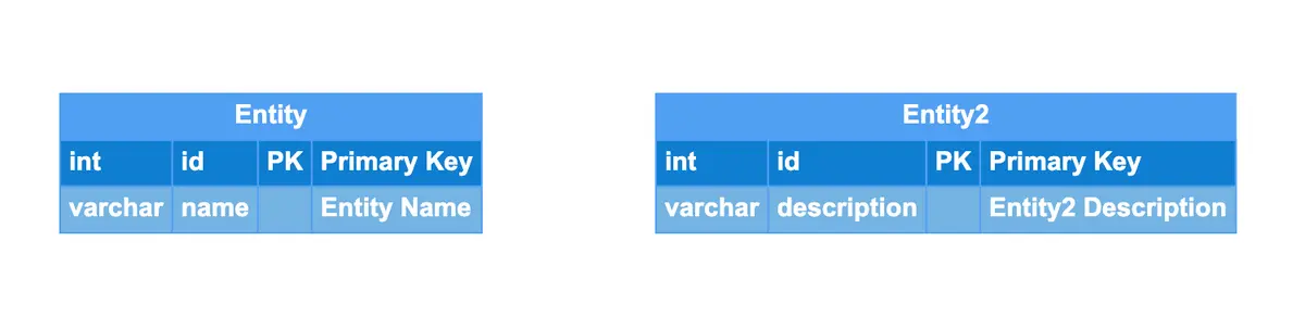
To create an entity, type the entity's name followed by its attributes.
Use the
TABbutton to add attributes. The format for attributes is:type,name,attribute key(PK, FK, or UK), anddescription(optional, enclosed in quotation marks).
Example:
Entity
int id PK "Primary Key"
varchar name "Entity Name"
Entity2
int id PK "Primary Key"
varchar description "Entity2 Description"
Make your own ER diagram in Gleek.
Defining Relationships:
Establish relationships between entities using Gleek's notation syntax.
Specify the multiplicity for each relationship to clearly define how entities relate to each other.
Setting and Customizing Multiplicity
Multiplicity in Gleek is defined using specific notations:
One-to-One (1:1):
{1}--{01}indicates one and only one on one side and zero or one on the other.Many-to-Many (M:N):
{0..n}--{0..n}indicates zero to many on both sides.{1..n}--{1..n}indicates one to many on both sides.{1..n}--{0..n}indicates one to many on one side and zero to many on the other.Many-to-One (M:1):
{0..n}--{1}indicates zero to many on one side and one and only one on the other.{1..n}--{1}indicates one to many on one side and one and only one on the other.{0..n}--{01}indicates zero to many on one side and zero or one on the other.{1..n}--{01}indicates one to many on one side and zero or one on the other.
Examples of ER Diagrams with Multiplicity Created in Gleek App
Use Case 1: Customer and Orders (One-to-Many)
In this example, a single customer can place multiple orders. This relationship is depicted as a one-to-many relationship.
Diagram:
Customer
int id PK "Customer ID"
varchar name "Customer Name"
Order
int id PK "Order ID"
int customerId FK "Customer ID"
Customer {1..n}--{1} Order

Online shopping system ER diagram
Use Case 2: Students and Courses (Many-to-Many)
This university management use case illustrates students enrolling in multiple courses, and each course having multiple enrolled students. This is a classic many-to-many relationship.
Diagram:
Student
int id PK "Student ID"
varchar name "Student Name"
Course
int id PK "Course ID"
varchar title "Course Title"
Student {0..n}--{0..n} Course

Student management system ER diagram
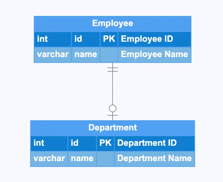
Use Case 3: Employee and Department (One-to-One)
Here, every employee belongs to one department, and each department is managed by one employee, showing a one-to-one relationship.
Diagram:
Employee
int id PK "Employee ID"
varchar name "Employee Name"
Department
int id PK "Department ID"
varchar name "Department Name"
Employee {1}--{01} Department
Best Practices and Tips for Effectively Representing Multiplicity
1. Ensure Clarity in Relationships:
- Use straightforward labels and lines to define relationships between entities. Ambiguous or overly complex connections can lead to misinterpretation.
- Group related entities together logically to enhance diagram readability.
2. Label Relationships and Multiplicity Clearly:
- Explicitly label all relationships with descriptive names and multiplicity indicators. For example, use
{1..n}--{0..n}where appropriate.- Consider adding annotations or comments directly within the diagram to explain particularly complex relationships or constraints.
3. Verify Accuracy of Multiplicity Constraints:
- Cross-check the multiplicity settings against real-world scenarios and business rules to ensure they are accurately represented.
- Discuss and review the ER diagram with stakeholders to confirm that it aligns with their understanding and requirements.
4. Use Consistent Notations and Symbols:
- Adhere to a consistent set of ERD symbols and notations throughout the diagram. This helps maintain clarity and makes the diagram easier to understand.
- Utilize standardized ERD notation practices, such as using crow's foot notation for relationships, to align with industry standards.
5. Simplify Where Possible:
- Avoid overloading your diagram with too many entities or attributes. Focus on core components and essential relationships.
- Use color-coding or different shapes to differentiate between types of entities (e.g., primary entities vs. associative entities), if the tool allows.
Common Mistakes to Avoid
1. Misrepresenting relationships with incorrect multiplicity:
- Double-check that the multiplicity constraints accurately depict the intended relationships. Incorrect multiplicity can lead to data integrity issues and logical inconsistencies.
- Be particularly cautious with many-to-many relationships, ensuring that they are correctly mapped using associative entities if required.
Make your own ER diagram in Gleek.
2. Overcomplicating diagrams with unnecessary entities or relationships:
- Resist the temptation to include every possible entity or attribute. Focus on those that are crucial to the system's functionality and goals.
- Simplifying the diagram by removing redundant or unnecessary entities will make it more readable and easier to maintain.
3. Ignoring the importance of consistency in using notations:
- Inconsistent notation can confuse readers and lead to misinterpretation. Stick to a single notation style throughout the diagram.
- Ensure that all team members are familiar with and use the same conventions when adding to or modifying the diagram.
4. Not considering scalability:
- Design your ER diagram with scalability in mind. Anticipate potential growth and changes in data volume and relationship complexity.
- Ensure that the multiplicity settings can accommodate future requirements without necessitating major redesigns.
Conclusion
Showing multiplicity in ER diagrams is crucial for accurately representing the relationships between entities. It ensures that your database design aligns with real-world scenarios and maintains data integrity by clearly defining how many instances of one entity can be associated with instances of another. By using appropriate notations and carefully setting multiplicity constraints, you can create a robust and reliable database structure.
We invite you to use the Gleek app for your ER diagram creation needs. With its intuitive interface and powerful features, Gleek makes it easy to define entities, set relationships, and customize multiplicity.
To help you get started quickly and effectively, Gleek provides a range of video tutorials and templates:
Video Tutorials: These tutorials offer step-by-step instructions on how to use Gleek's features, covering everything from basic entity creation to advanced multiplicity settings. This ensures you can make the most of the tool.
Templates: Explore pre-designed templates within the Gleek app to kickstart your projects. These templates include various common ER diagram structures that you can customize to fit your specific needs.
With these resources, you can accelerate your learning curve and enhance your diagramming capabilities, making it easier to create comprehensive and accurate ER diagrams.
Related posts
All about ER model cardinality with examples
Derived Attributes in ER diagrams: A comprehensive exploration
ER diagram for an E-commerce website with Gleek's AI chat
Primary keys vs. unique keys: Fundamental differences
Relational schema vs. ER diagrams: A detailed comparison
Guide to entity-relationship diagram notations & symbols
What is the entity-relationship diagram in database design?
Composite and other attributes in the entity-relationship model