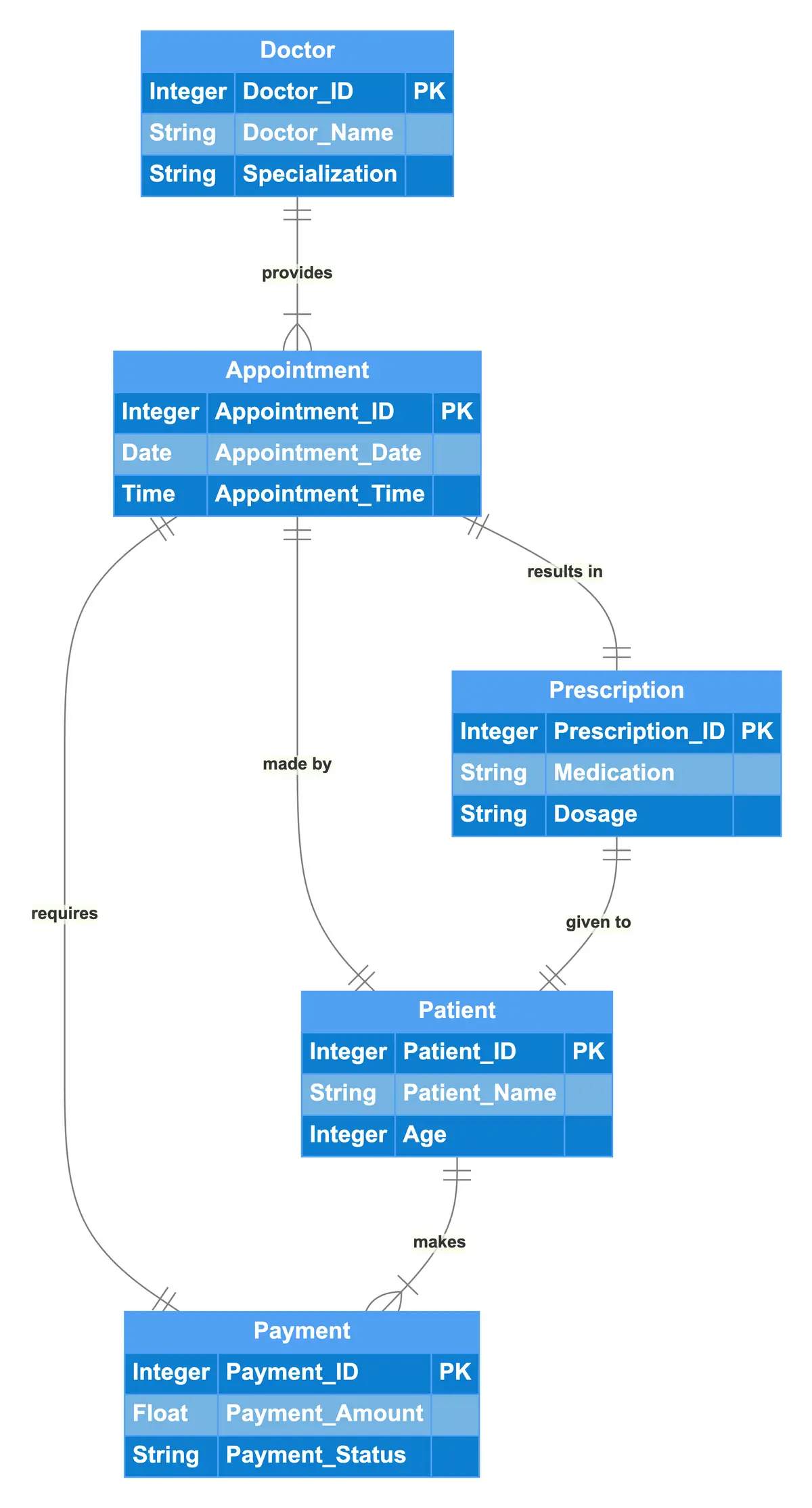
This ER diagram represents an Online Doctor Appointment System, featuring entities such as Doctor, Patient, Appointment, Payment, and Prescription. Each Doctor is uniquely identified and has attributes including name and specialization. Patients, identified by a unique ID and age, can schedule multiple Appointments. Each Appointment links a Patient to a specific Doctor and includes details like date and time. Appointments also necessitate a Payment, which is associated with a specific amount and status. Furthermore, each Appointment results in a Prescription detailing medication and dosage, which is given to the corresponding Patient. The relationships among these entities illustrate the workflow from scheduling appointments to payments and prescriptions.

Edit this diagram in Gleek
Online doctor appointment system diagram code in Gleek
Doctor
Integer Doctor_ID PK
String Doctor_Name
String Specialization
Patient
Integer Patient_ID PK
String Patient_Name
Integer Age
Appointment
Integer Appointment_ID PK
Date Appointment_Date
Time Appointment_Time
Payment
Integer Payment_ID PK
Float Payment_Amount
String Payment_Status
Prescription
Integer Prescription_ID PK
String Medication
String Dosage
Doctor {1}-provides-{1..n} Appointment
Appointment {1}-made by-{1} Patient
Appointment {1}-results in-{1} Prescription
Appointment {1}-requires-{1} Payment
Patient {1}-makes-{1..n} Payment
Prescription {1}-given to-{1} Patient
About ER diagrams
We often make an entity-relationship (ER) diagram, ERD, or entity-relationship model, in the early stages of designing a database. An ERD is perfect for quickly sketching out the elements needed in the system. The ERD explains how the elements interact. ER diagrams can be shared with colleagues. Their simplicity makes them ideal even for non-technical stakeholders.
Similar ER diagram examples
Banking system entity-relationship diagram
Online Food Delivery entity-relationship diagram
Travel management system Er diagram
Online Movie Streaming Platform entity-relationship diagram