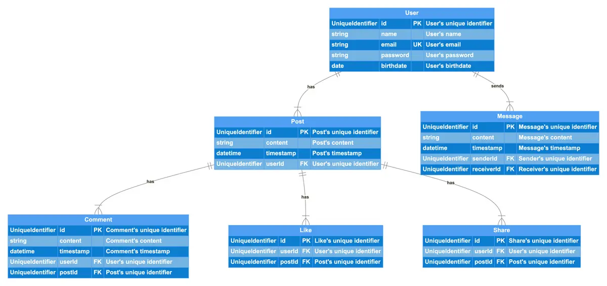
The ER diagram represents a Social Media Platform, where users can create posts, interact with content, and communicate with each other. Each User has a unique identifier, name, email, password, and birthdate. Users can create Posts, which contain textual content and a timestamp. Other users can engage with posts by adding Comments, expressing appreciation through Likes, and sharing content via Shares. The platform also supports direct communication between users through Messages, which store the sender, receiver, content, and timestamp. This ER diagram illustrates the core functionalities of a social media system, enabling content creation, interaction, and messaging between users.
Edit this diagram in Gleek
Social Media Platform diagram code in Gleek
User
UniqueIdentifier id PK "User's unique identifier"
string name "User's name"
string email UK "User's email"
string password "User's password"
date birthdate "User's birthdate"
Post
UniqueIdentifier id PK "Post's unique identifier"
string content "Post's content"
datetime timestamp "Post's timestamp"
UniqueIdentifier userId FK "User's unique identifier"
Comment
UniqueIdentifier id PK "Comment's unique identifier"
string content "Comment's content"
datetime timestamp "Comment's timestamp"
UniqueIdentifier userId FK "User's unique identifier"
UniqueIdentifier postId FK "Post's unique identifier"
Like
UniqueIdentifier id PK "Like's unique identifier"
UniqueIdentifier userId FK "User's unique identifier"
UniqueIdentifier postId FK "Post's unique identifier"
Share
UniqueIdentifier id PK "Share's unique identifier"
UniqueIdentifier userId FK "User's unique identifier"
UniqueIdentifier postId FK "Post's unique identifier"
Message
UniqueIdentifier id PK "Message's unique identifier"
string content "Message's content"
datetime timestamp "Message's timestamp"
UniqueIdentifier senderId FK "Sender's unique identifier"
UniqueIdentifier receiverId FK "Receiver's unique identifier"
User {1}-has-{1..n} Post
User {1}-sends-{1..n} Message
Post {1}-has-{1..n} Comment
Post {1}-has-{1..n} Like
Post {1}-has-{1..n} Share
About ER diagrams
We often make an entity-relationship (ER) diagram, ERD, or entity-relationship model, in the early stages of designing a database. An ERD is perfect for quickly sketching out the elements needed in the system. The ERD explains how the elements interact. ER diagrams can be shared with colleagues. Their simplicity makes them ideal even for non-technical stakeholders.
Similar ER diagram examples
Online store entity-relationship diagram
Employee management system entity-relationship diagram
Banking system entity-relationship diagram
Travel management system Er diagram
College management system ER diagram