
Inheritance is a foundational concept in object-oriented design, serving as a mechanism to establish hierarchical relationships between classes within class diagrams. At its core, inheritance allows for the organization of complex systems into more manageable and interconnected categories, where classes share, extend, and modify behaviors and attributes of other classes.
Introduction to Inheritance in Class Diagrams
The essence of inheritance can be observed through the relationships between a superclass (also known as the parent class) and subclass (or child class). A superclass is a general category that outlines common attributes and methods, which are then inherited by the more specialized subclasses. This mechanism not only fosters code reuse—eliminating redundancy by allowing subclasses to utilize and extend the functionality of their superclasses—but also establishes a natural hierarchy within the system's architecture.
Find out about other UML relationships in our article: UML relationships explained
By utilizing inheritance, developers can build modular and scalable systems where changes to a superclass are automatically applied to subclasses, ensuring uniformity and minimizing errors. In the next section, we will explore how inheritance is visually represented in class diagrams, detailing the symbols and notations that indicate these hierarchical connections to deepen our comprehension of their structural implications.
Make your own UML class diagram with Gleek.
Understanding the Inheritance Line in UML Diagrams
As mentioned in the previous section, inheritance in UML (Unified Modeling Language) class diagrams is meticulously depicted to convey the hierarchical relationships between classes clearly and effectively. The inheritance line, or the generalization relationship, plays a central role in this representation. Traditionally, it's shown as a solid line with a hollow arrowhead, which points from the subclass to the superclass. This visual indicator is more than just a line; it's a symbol of the subclass inheriting attributes and behaviors from the superclass, signifying a 'is a' relationship between the two.
The hollow arrowhead is specifically designed to indicate the directionality of the relationship—highlighting the flow of properties and methods from the superclass to its subclasses. Such a clear-cut representation aids developers and architects in grasping the structure of the software system at a glance, ensuring an intuitive understanding of its architecture without the need to dig through code or extensive documentation.
Read a blog post on Class diagram arrow types.
Transitioning to the Gleek app, inheritance is represented in a manner that aligns with the conventional UML standards yet simplifies the process of diagram creation. For example, consider a simple class hierarchy where Vehicle is a superclass and Car is its subclass. In Gleek, one might represent the inheritance relationship between them as follows:
Vehicle --*> Car
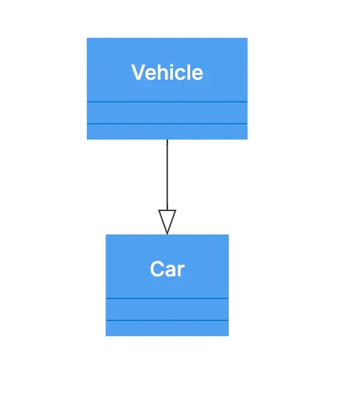
This line effectively communicates that Car inherits from Vehicle, encapsulating the essence of their relationship in a single, easily understood diagrammatic element.
Best Practices for Representing Inheritance
When crafting class diagrams to depict inheritance, particularly through the use of the Gleek app, several best practices should be followed to ensure clarity, simplicity, and effectiveness. Let's list them:
1. Strive for clarity and simplicity
Use clearlabeling: Ensure that each class name is clear and descriptive. Utilize simple notation like "--*>" for inheritance to maintain visual simplicity and clarity.
Minimalistic design: Avoid adding unnecessary attributes or methods in the overview diagrams to keep the focus on the inheritance relationships.
2. Avoid overly complex hierarchies
Flatten hierarchies where possible: While some complexity is inevitable, try to minimize deep inheritance trees as they can become confusing and hard to maintain.
Segment complex diagrams: If dealing with a complex system, break it down into smaller, more focused diagrams that each capture a portion of the system’s hierarchy.
3. Ensure understandability
Consistent orientation: Maintain a consistent direction for inheritance arrows (e.g., top-to-bottom or left-to-right) across all diagrams to help readers quickly grasp the structure.
Use annotations wisely: Leverage annotations or notes to explain peculiar inheritance decisions or to highlight abstract classes and interfaces.
Make your own UML class diagram with Gleek.
4. Maintain UML standards consistency
Adhere to UML symbols: Even when using Gleek’s simplified syntax, keeping your diagrams aligned with UML standards ensures they are understandable by those familiar with UML.
Regular reviews: Periodically review diagrams for adherence to UML guidelines, particularly when sharing with stakeholders or integrating into documentation.
Examples of Inheritance used in Class Diagrams
1. Abstract Classes and Concrete Subclasses
Scenario: An abstract class Shape with concrete subclasses Circle, Rectangle, and Triangle.
Gleek representation:
Shape --*> CircleShape --*> RectangleShape --*> Triangle
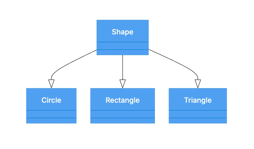
Key point: The Shape class can include abstract methods like draw() or area(), which are then implemented by the concrete subclasses. This structure clearly conveys that Circle, Rectangle, and Triangle are all specific types of Shape.
2. Multiple Levels of Inheritance
Scenario: A base class Employee with a subclass Manager, which is further subclassed into DepartmentManager and ProjectManager.
Gleek representation:
Employee --*> ManagerManager --*> DepartmentManagerManager --*> ProjectManager
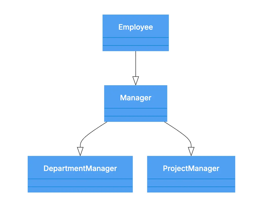
Key point: This diagram showcases a multi-level inheritance hierarchy, depicting how managerial roles inherit from a general Employee base class, with further specialization into departmental or project-focused managers.
3. Implementing Multiple Interfaces
Scenario: A class Smartphone that implements both Camera and GPS interfaces.
Gleek representation:
Assuming Gleek supports interface implementation notation, you might use a different style or prefix to denote interfaces, like:
Camera --*> SmartphoneGPS --*> Smartphone
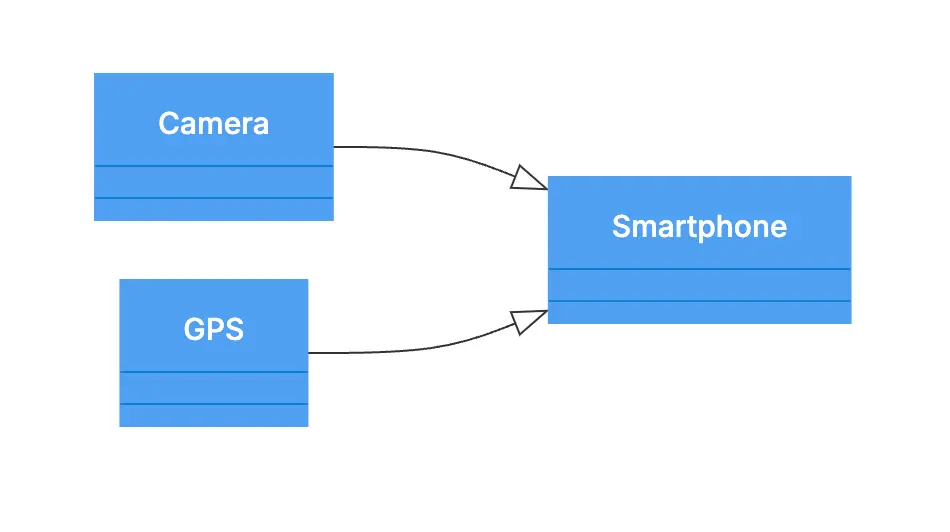
Key point: This example highlights how a single class can inherit behavior from multiple sources, showcasing the versatility of object-oriented design.
4. Interface Hierarchy
Scenario: An interface Vehicle with subinterfaces LandVehicle and WaterVehicle, and concrete classes Car and Boat implementing the respective subinterfaces.
Gleek representation:
Vehicle --*> LandVehicleVehicle --*> WaterVehicleLandVehicle --*> CarWaterVehicle --*> Boat
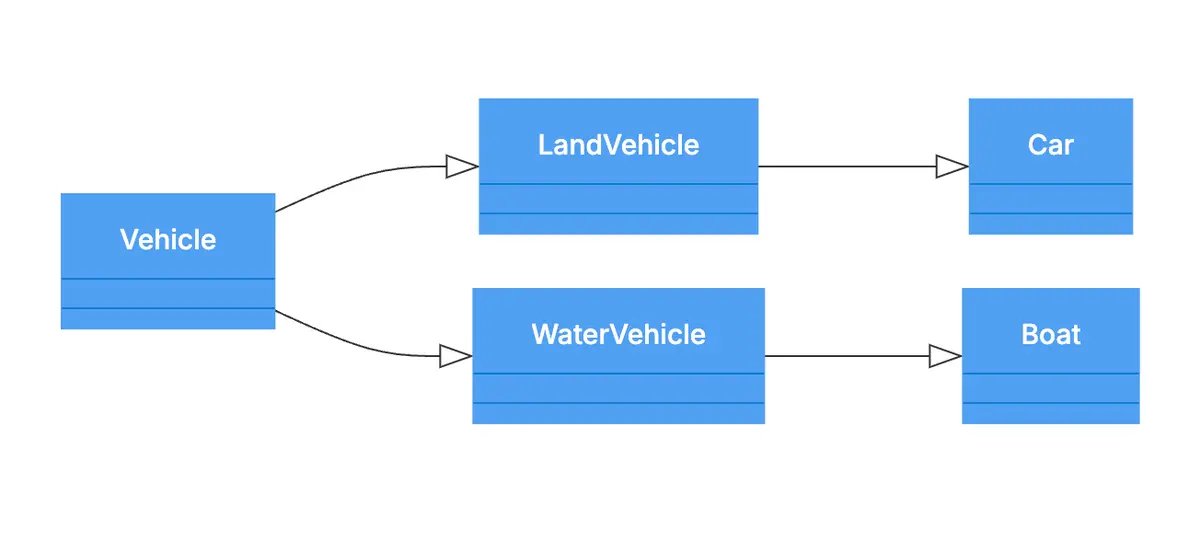
Key point: Interfaces, like classes, can have their own hierarchies. This diagram illustrates an inheritance chain that goes from very general interfaces down to specific implementations.
Learn the difference between aggregation and composition relationships in UML.
Common Mistakes to Avoid
Creating effective class diagrams involves following best practices and being mindful of common pitfalls that can undermine clarity and accuracy. Here are some detailed explanations of these mistakes and how to avoid them:
Circular Dependencies
Issue: Circular dependencies occur when two or more classes inherit from each other directly or indirectly, creating a loop. For example, if ClassA inherits from ClassB and ClassB inherits from ClassA, this forms a circular dependency.
Why it’s problematic:
Logical inconsistency: Inheritance implies a hierarchical relationship where one class is a specialization of another. Circular dependencies violate this logic, as it suggests mutual specialization, which is conceptually flawed.
Implementation issues: Most programming languages do not support circular inheritance, leading to compilation errors or runtime failures. It complicates dependency resolution during object creation and class loading.
Make your own UML class diagram with Gleek.
Solution: Always ensure that inheritance relationships form a directed acyclic graph (DAG), meaning there are no cycles. Regularly review your diagrams for any loops and refactor the design to eliminate these dependencies.
Related topic: UML Dependency: Managing Relationships in Software Design
Overloaded Diagrams
Issue: Overloaded diagrams are those that include too many classes, relationships, or details in a single view, making them difficult to read and understand.
Why it’s problematic:
Visual clutter: Excessive information can clutter the diagram, making it hard to identify key relationships and structures.
Cognitive load: Viewers may struggle to process and comprehend the diagram, reducing its effectiveness as a communication and documentation tool.
Solution:
Focus on core relationships: When representing inheritance, concentrate on the essential superclass-subclass relationships. Exclude unrelated details that do not contribute to understanding these core hierarchies.
Segment complex structures: Break down complex systems into smaller, more focused diagrams. Each diagram should cover a specific aspect or module of the system, facilitating easier comprehension.
Use layers or views: If your tool supports it, create different layers or views for various aspects (e.g., one for inheritance, another for associations).
Inconsistent Notation
Issue: Using multiple symbols or styles inconsistently within or across diagrams can lead to confusion. For instance, switching between different arrow types or line styles to denote the same kind of relationship without clear rationale.
Why it’s problematic:
Reader confusion: Inconsistent notation makes it difficult for viewers to understand the relationships and logic represented. They may misinterpret the diagram, leading to misunderstandings about the system’s design.
Documentation issues: Consistency is crucial for maintaining clear and professional documentation. Inconsistent diagrams can appear unstructured and unprofessional.
Solution:
Standardize notation: Decide on a consistent set of symbols and styles for all elements in your diagrams and stick with them. Use the same type of arrow for inheritance (e.g., "--*>") throughout all diagrams.
Create a style guide: Develop a style guide for your diagrams, outlining the symbols and notations used for various relationships and elements. Ensure all team members adhere to this guide.
Regular reviews: Periodically review diagrams to ensure consistency and adherence to established standards. Make adjustments as needed to maintain uniformity.
By being aware of these common mistakes and taking proactive steps to avoid them, you can ensure that your class diagrams are both accurate and easy to understand.
Tools like the Gleek app provide straightforward syntax and features that support best practices, helping you create clear, professional diagrams. Mastering inheritance in class diagrams is crucial for effective object-oriented design, promoting modularity, scalability, and maintainability. By understanding the relationships between superclasses and subclasses and using proper UML conventions, developers can represent their systems' hierarchical structures clearly.
Overall, understanding and properly implementing inheritance in class diagrams greatly enhances the clarity and structure of software design. Using tools like Gleek simplifies this process, ensuring consistency and clarity. Following best practices—such as maintaining simplicity, avoiding complex hierarchies, ensuring understandability, and adhering to UML standards—enhances the accuracy and readability of your diagrams. This ultimately contributes to better software design and development.
Experience the power of effective system modeling by creating your first class diagram with different connections like Inheritance, Multiplicity, and Association in the Gleek app. Explore how inheritance can be visualized and applied in your projects, paving the way for more robust and coherent designs.
Related posts
Class diagram for an ATM system: a step-by-step guide
UML class diagram arrow types: explanations and examples
UML Essentials: Aggregation vs Composition Explained
How do we create a Class diagram for a Library Management system?
UML relationships explained: Dependency, Realization, Association
Hospital management system class diagram using Gleek App