
When designing software systems, understanding how different components interact is extremely important. UML (Unified Modeling Language) provides a standardized way to represent these interactions through various diagrams, including class diagrams. One fundamental aspect of these diagrams is multiplicity, which defines how many instances of one class can be associated with instances of another class. Grasping multiplicity is essential for accurate system modeling and effective communication among developers, designers, and stakeholders.
Introduction to Multiplicity in UML
Multiplicity in UML class diagrams specifies the cardinality of relationships between classes. This tells you how many instances of a class can be linked to a single instance of another class. For example, it can describe whether a customer can place multiple orders or just one, or whether a library can have many books or only a few. Understanding these relationships helps prevent errors and ensures that the system behaves as expected. It also helps in planning how data will be stored and managed within databases, as well as how objects will interact in object-oriented programming.
Make your own UML class diagram with Gleek.
Properly defined multiplicity ensures accurate data modeling and helps prevent logical errors that could arise from incorrect assumptions about object relationships. By clearly illustrating these relationships, multiplicity aids in creating robust, maintainable, and scalable software solutions.
In the next section, we will discuss the visual representation of multiplicity in class diagrams, exploring how different notations convey relationship cardinality.
How to Read Multiplicity in a Class Diagram: Notation Explained
In UML class diagrams, multiplicity is represented using specific notation that indicates the number of instances in a relationship. The most common symbols include:
1 (One): A single instance of a class. This notation means that each instance of the class at one end of the association must be associated with exactly one instance of the class at the other end. It enforces a strict one-to-one relationship.
0..1 (Zero or One): Zero or one instance of a class. This indicates that an instance of the class at one end of the association can be associated with either no instances or one instance of the class at the other end. It represents an optional relationship where the association is not mandatory.
0.. (Zero or Many): Zero or more instances of a class. This notation signifies that an instance of the class at one end of the association can be associated with zero, one, or many instances of the class at the other end. It denotes a flexible relationship that can vary in the number of instances.
1.. (One or Many): At least one instance of a class. This indicates that an instance of the class at one end of the association must be associated with at least one instance of the class at the other end, but can be associated with many. It ensures a mandatory relationship with no upper limit on the number of instances.
Related topic: Aggregation vs Composition Explained
These notations are placed near the ends of association lines connecting two classes to denote the possible number of instances that can participate in the relationship. They provide a clear and concise way to specify the constraints and nature of the associations between classes in a UML class diagram.
Tips for Reading and Understanding Multiplicity Notations in Class Diagrams
Identify relationship lines: Start by identifying the lines connecting different classes. These lines represent associations, and the multiplicity notations are usually placed near the ends of these lines.
Read the notations: Look for the multiplicity symbols (e.g., 1, 0..1, 0.., 1..) at both ends of the relationship lines. These notations tell you how many instances of each class can participate in the relationship.
Interpret the meaning: Use the definitions of the multiplicity symbols we discussed in the previous section to understand the nature of the relationship:
1means exactly one instance.0..1means zero or one instance (optional relationship).0..*means zero or more instances (flexible relationship).1..*means one or more instances (mandatory relationship).
Consider the context: Think about the real-world scenario being modeled. Understanding the context can help clarify why certain multiplicity notations are used.
Check for consistency: Ensure that the multiplicity notations make sense in the context of the entire diagram. Inconsistent notations can indicate errors in the diagram.
Use tools: Utilize diagramming tools like Gleek to help visualize and validate the multiplicity in your class diagrams. These tools often provide features to ensure notations are applied correctly and consistently.
Learn more about association relationship in UML.
Using Gleek App: Simplifying Multiplicity Notations with Gleek
The Gleek app is a powerful tool that simplifies the creation and visualization of UML diagrams, including class diagrams with multiplicity notations. Gleek's intuitive interface allows users to easily design and modify diagrams, making it accessible for both beginners and experienced developers.
By automating much of the drawing process, Gleek helps ensure that multiplicity notations are correctly applied and visually clear, reducing the risk of errors and enhancing overall productivity.
Using Gleek, you can quickly create diagrams that clearly represent the relationships and multiplicities between classes, aiding in better communication and understanding among team members. This tool streamlines the design process, making it easier to focus on the core aspects of software development and design.
Real-Life Examples and Visual Representations
To better understand multiplicity, consider the following real-life examples and their visual representations in class diagrams:
One-to-One relationship:
Example: Each person has exactly one passport.
Notation:
Person{1}--{1}Passport
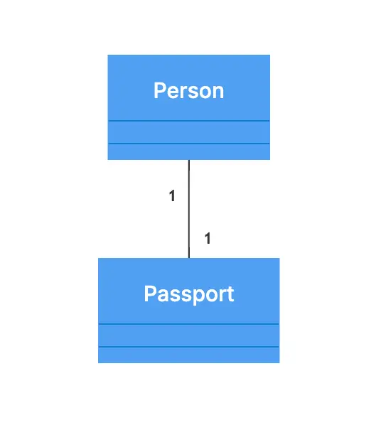
Passport automation process class diagram template
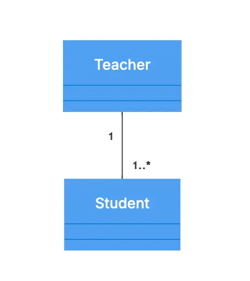
One-to-Many relationship:
Example: A teacher can teach multiple students.
Notation:
Teacher{1}--{1..*}Student
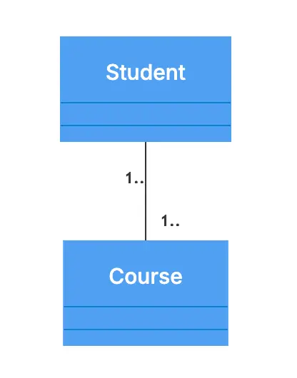
Many-to-Many relationship:
Example: Students can enroll in multiple courses, and each course can have multiple students.
Notation: Student{1..}--{1..}Course
Make your own UML class diagram with Gleek.
Check out our recent tutorial on creating a University management system using the Gleek app.
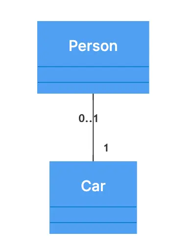
Zero or One:
Example: A person may or may not own a car.
Notation:
Person{0..1}--{1}Car
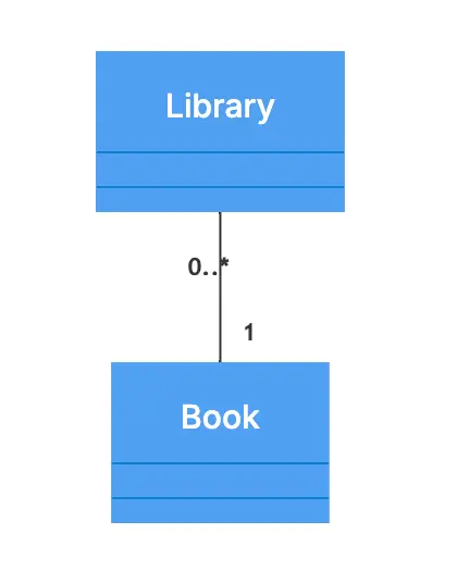
Zero or More:
Example: A library can have zero or more books.
Notation:
Library{0..*}--{1}Book
Related post: Step-by-step guide on Library management system class diagram.
These visual representations help clarify the nature of relationships between different classes, ensuring that developers can model and implement systems accurately.
Practical Applications of Multiplicity: Case Studies and Real-world Impacts
Multiplicity in UML class diagrams plays a significant role in various real-world applications, impacting how systems are designed, implemented, and maintained. Here are a few case studies that highlight its importance:
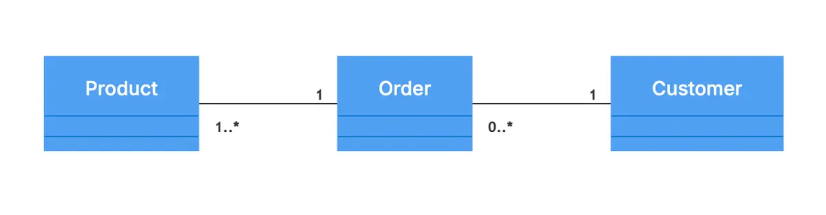
E-commerce Platform:
Scenario: An e-commerce platform needs to model relationships between Customer, Order, and Product.
Make your own UML class diagram with Gleek.
Multiplicity:
Customer{1}--{0..*}Order: Each customer can place zero or more orders.
Order{1}--{1..*}Product: Each order contains one or more products.
Check out Online shopping class diagram template.
Impact: Properly modeling these relationships ensures that the system can handle multiple orders per customer and multiple products per order, leading to accurate tracking and inventory management.
Scenario: A hospital system tracks relationships between Doctor, Patient, and Appointment.
Multiplicity:
Doctor{1}--{0..*}Appointment: A doctor can have zero or more appointments.
Patient{1}--{0..*}Appointment: A patient can have zero or more appointments.
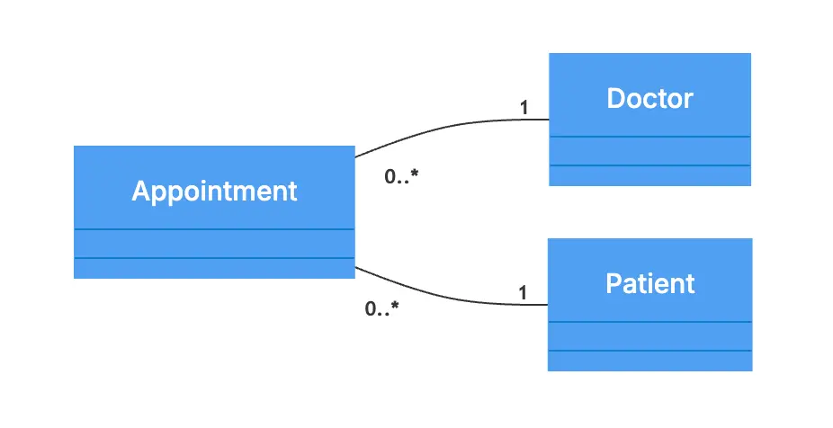
Impact: Accurate multiplicity ensures that the system can efficiently manage schedules, preventing double-booking and enabling better resource allocation.
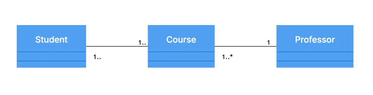
Educational Institution Management:
Scenario: In a university management system, a university needs to model relationships between Professor, Course, and Student.
Multiplicity:
Professor{1}--{1..*}Course: A professor teaches one or more courses.
Course{1..}--{1..}Student: Each course can have multiple students, and each student can enroll in multiple courses.
University management system class diagram
Impact: This ensures that the system can handle complex enrollment scenarios, facilitating efficient course management and student tracking.
Best Practices for Modeling Relationships
To effectively utilize multiplicity in UML class diagrams, follow these best practices:
Clearly define relationships: Ensure that each relationship is clearly defined with appropriate multiplicity notations. Ambiguities can lead to incorrect implementations and misunderstandings.
Align with business rules: The multiplicity in your class diagrams should align with the business rules and requirements. For example, if a business rule states that a customer can only place one order at a time, ensure that this is reflected in the diagram.
Use descriptive names: Name classes and relationships descriptively to convey their purpose and interactions clearly. This enhances readability and understanding for all stakeholders.
Validate with stakeholders: Regularly validate the class diagrams with stakeholders to ensure that the multiplicity and relationships accurately reflect real-world scenarios and business needs.
Keep diagrams simple: Avoid overly complex diagrams by breaking down large systems into smaller, manageable components. This makes it easier to understand and maintain the diagrams.
Document assumptions: Document any assumptions made during the modeling process. This helps in future maintenance and provides context for decisions.
By following these best practices, you can create accurate, effective UML class diagrams that enhance communication, reduce errors, and contribute to the successful implementation of software systems.
Conclusion
Multiplicity in UML class diagrams is essential for accurately modeling relationships between classes, impacting database design and object-oriented programming.
Tools like the Gleek app simplify creating UML diagrams, making it easy to visualize and apply multiplicity. Gleek’s intuitive interface and powerful features help ensure accurate and clear notations.
We encourage designers and developers to deepen their understanding of multiplicity by using the Gleek app. This hands-on approach enhances design skills and comprehension. Start modeling effective systems with Gleek today and bring clarity to your projects.
Related posts
UML Dependency: Managing Relationships in Software Design
Class diagram for an ATM system: a step-by-step guide
UML class diagram arrow types: explanations and examples
UML Essentials: Aggregation vs Composition Explained
How do we create a Class diagram for a Library Management system?
Mastering inheritance in class diagrams
UML relationships explained: Dependency, Realization, Association
Hospital management system class diagram using Gleek App