
UML, or Unified Modelling Language, is a visual diagramming language used to represent the design of systems or processes. It is especially useful for designing software and databases. Creating a UML diagram before any code is written is an efficient way for programmers to keep track of all the components involved and how they relate to each other. However, UML diagrams are increasingly being used for less formal business purposes, especially for the rapid communication of ideas between teams and stakeholders.
What UML diagram types can be created?
UML is now at version 2.5 and it allows for 14 different types of diagrams. These types are divided into two categories: structure diagrams and behavior diagrams. Let’s briefly summarize each diagram type before exploring the most popular UML diagrams.
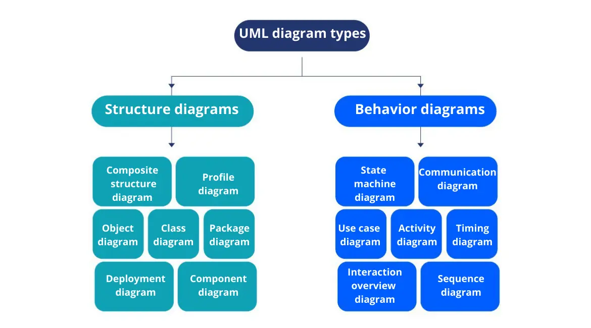
Structure diagrams
Class diagram
Software engineers use class diagrams to show the classes, attributes, methods in a system and to describe their relationships to each other. Class diagrams enable developers to sketch a static view of a system before creating it.
Make your own UML diagram with Gleek.
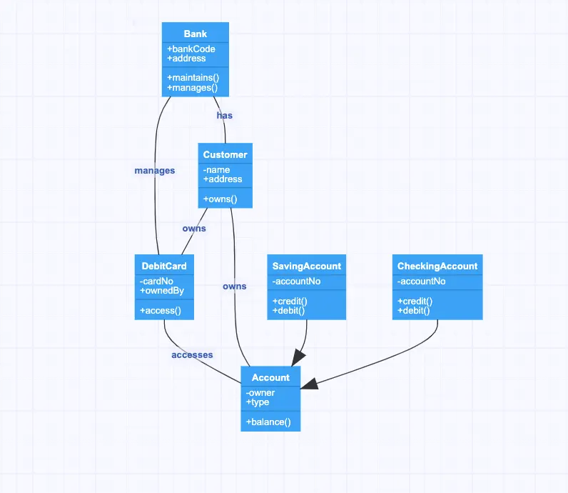
Source: Bank diagram example
Object diagram
Again a more concrete form of diagram, object diagrams are focused on representing a system at a particular point in time. The object diagram shows the real-world instances of classes and the relationships between these instances.
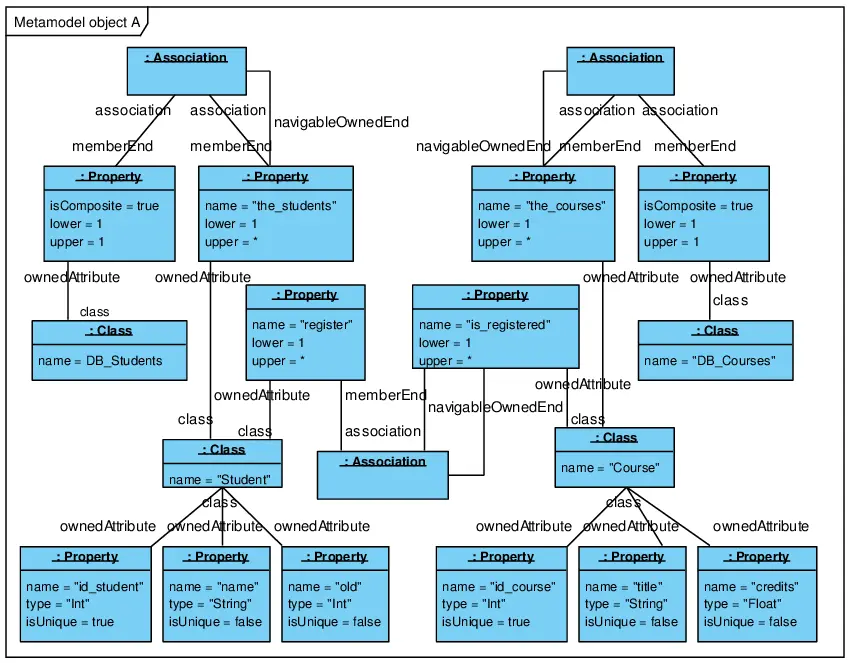
Source: Object Diagram of the Example
Component diagram
In any software system, the various components can be composed of other, smaller components. A component diagram shows how these individual software components interact and the dependencies between them.
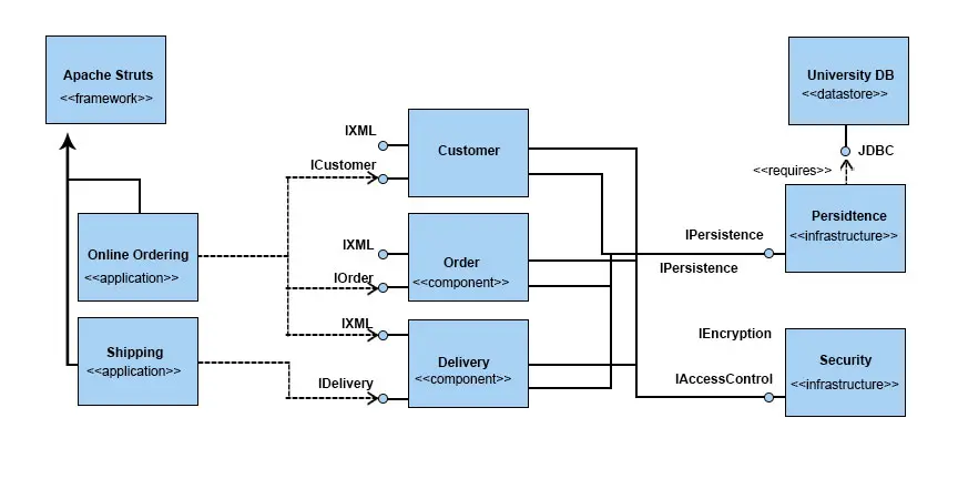
Source: Introduction to UML Component Diagram
Deployment diagram
Rather than dealing with abstract elements in a system, a deployment diagram models the physical deployment of the components, or nodes, in that system. It is concerned with real-world entities such as servers and computing resources, with the interaction between them described in terms of connectivity and APIs.
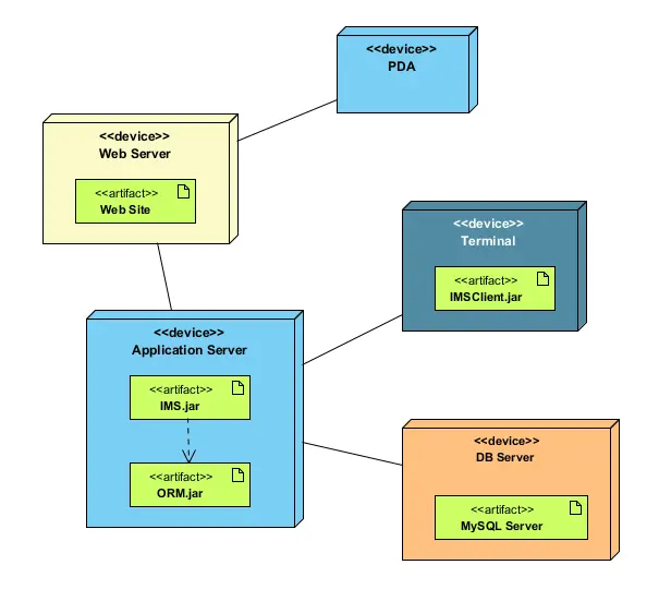
Source: Deployment diagram
Package diagram
Packages in UML are hierarchical groupings of elements that allows for manageable organization of the various components in a system. For instance, packages can enable the developer to represent the different layers of code used in the system and how these different layers interact.
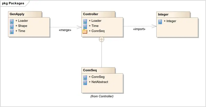
Source: UML 2 Tutorial – Package Diagram
Composite structure diagram
This type of diagram is concerned with the internal structure of a class, or classifier, and how its internal parts collaborate via particular ports at runtime to achieve their desired purpose.

Source: Composite Structure Diagrams
Profile diagram
Profile diagrams enable the extension of a UML model by means of what are called stereotypes. These stereotypes can be assigned to individual UML elements or connectors and used when modeling particular domains.
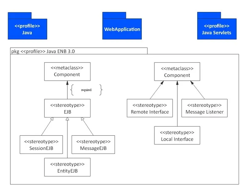
Source: Profile Diagram Explained
Behavior diagrams
Sequence diagram
Based on the modeling of interactions between objects in a particular time sequence, these diagrams are used to give an overview of how the different parts of a system interact over time and how processes are carried out.
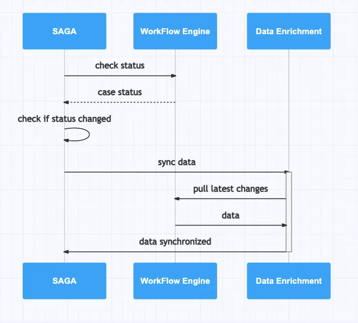
Source: State Synchronization
Use case diagram
These are simple diagrams that show how a user can interact with a system. They depict actors and the actions they can take to have an impact on the system.
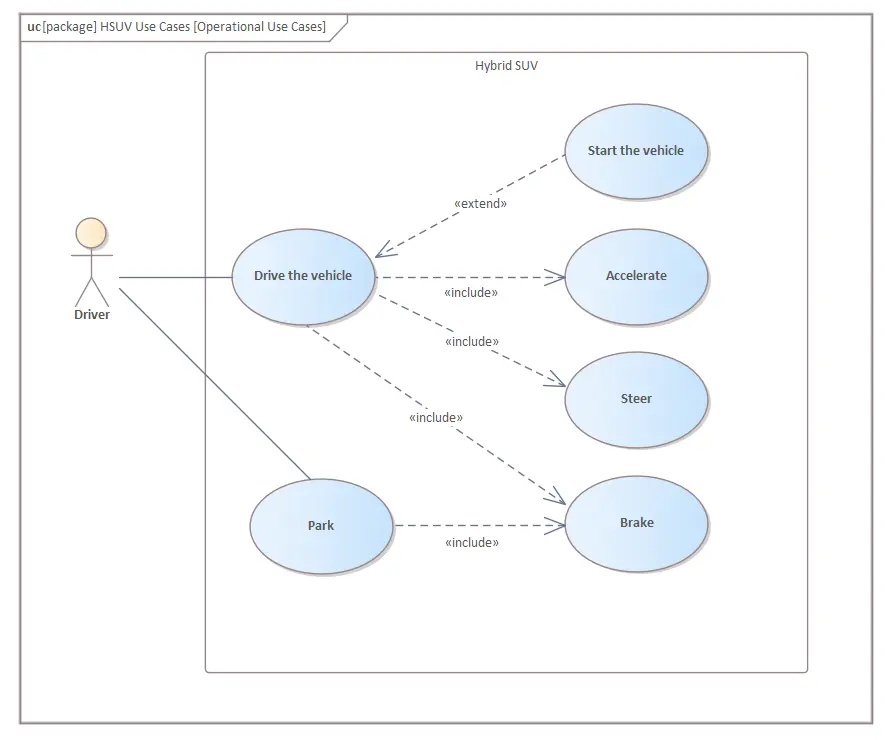
Source: Use Case Diagram
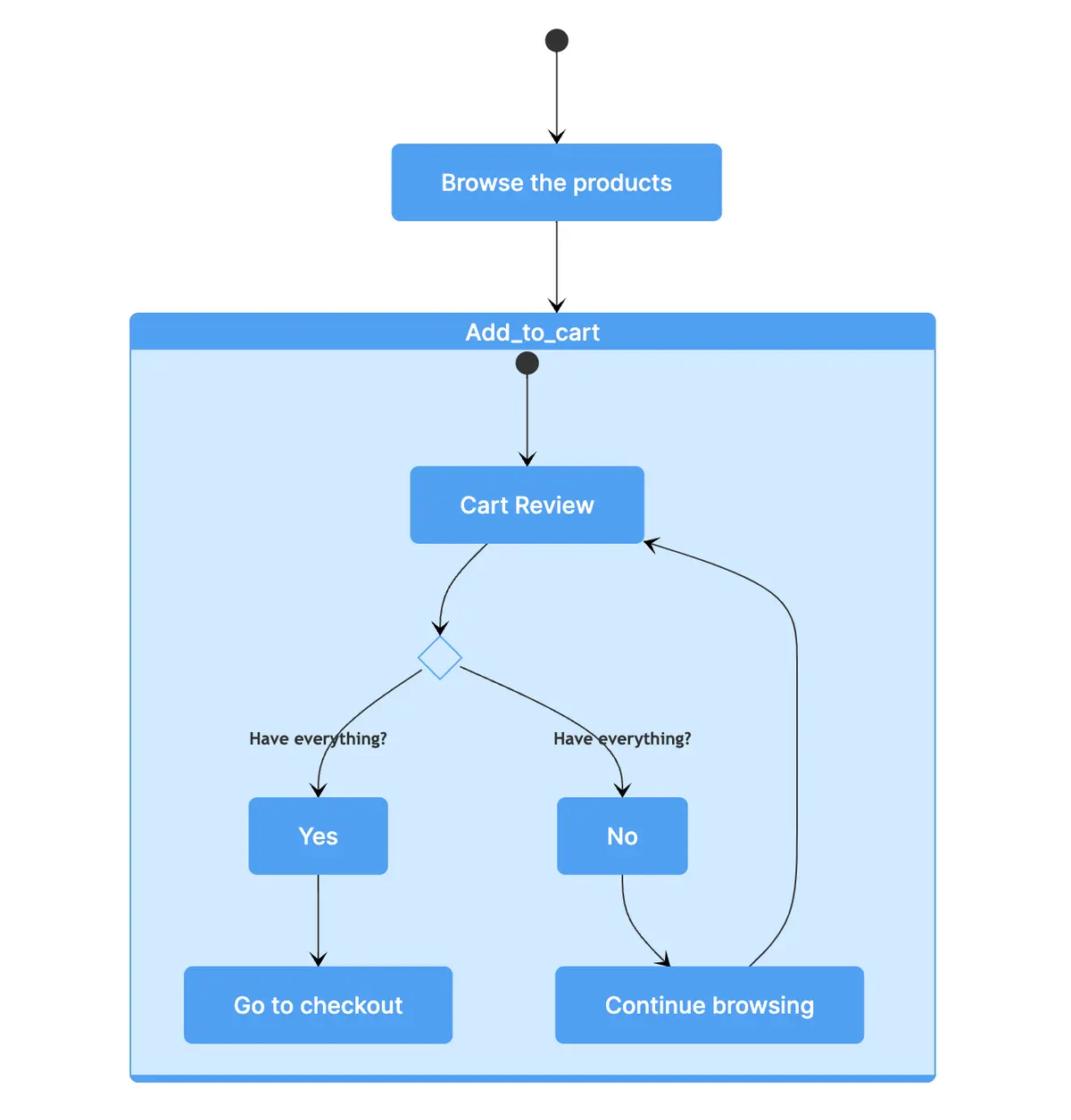
Activity diagram
Used to graphically show the workflows of activities and actions, activity diagrams are concerned with the flow of control in a system and how decisions and conditions can lead to branching in the system.
Related blog post: What is the difference between the Activity diagram and sequence diagram?
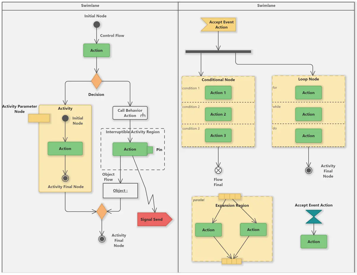
Source: UML Activity Diagram Tutorial
State machine diagram
Designed to capture the dynamic nature of a system and how it can change from one state to another, state machine diagrams show possible states and transitions along with the actions or events that cause the system to change states.
Communication diagram
A communication diagram is similar to a sequence diagram, as it shows the dynamic interactions between objects over time, but it gives more of an overview of the entire system, with less focus on timing.
Source: What is Communication Diagram?
Interaction overview diagram
Another diagram more concerned with the holistic view of a system, the interaction overview diagram is similar to the activity diagram, in that it visualizes the sequence of activities and flow of control. But it also allows for frames around activities that enable complex inline interactions to be described.
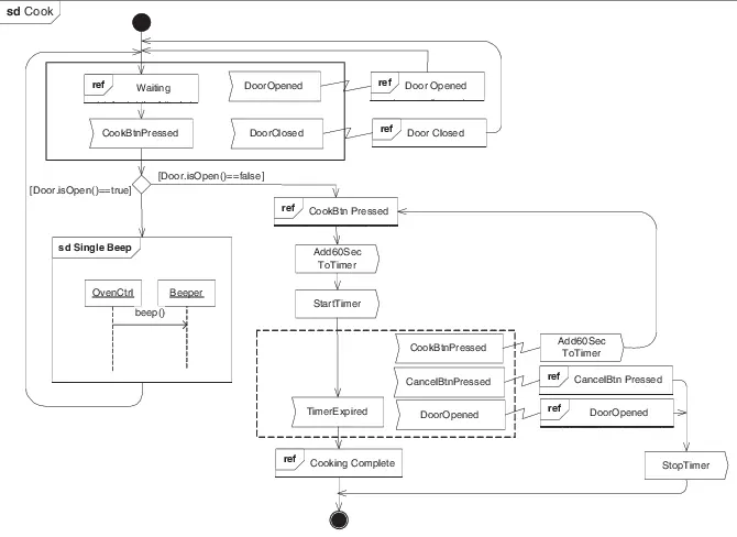
Source: The revised interaction overview diagram
Timing diagram
Somewhat like a sequence diagram, timing diagrams show the behavior of objects in the system over time. However, the timing diagram uses a linear time axis that moves from left to right and shows how conditions change in terms of levels of lifelines. Timing diagrams are, as you might expect, useful for understanding timing constraints.
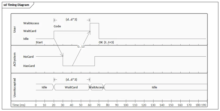
Source: UML Timing Diagram
What are the most common UML diagrams?
For everyday use, three types of UML diagrams are the most popular:
Class diagram
Object diagram
Sequence diagram
When should you use a class diagram?
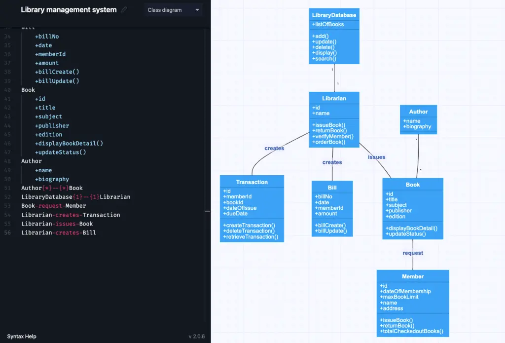
Developers use class diagrams to describe the static structure of a system. A class diagram is like a blueprint that shows the classes, attributes, methods (or operations) in the system and their relationships to each other.
Class diagrams are an important building block of object-oriented code and are especially useful for making sure that all team members understand how the system will work. With just a handful of different class diagram arrows, a developer can quickly and clearly explain very complex interactions between the parts of the system.
Make your own UML class diagram with Gleek.
Example of a class diagram
Check out our detailed step-by-step guide to creating a class diagram of a library management system.
Read on library management example for sequence diagram.
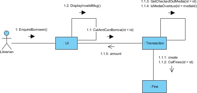
When should you use a sequence diagram?
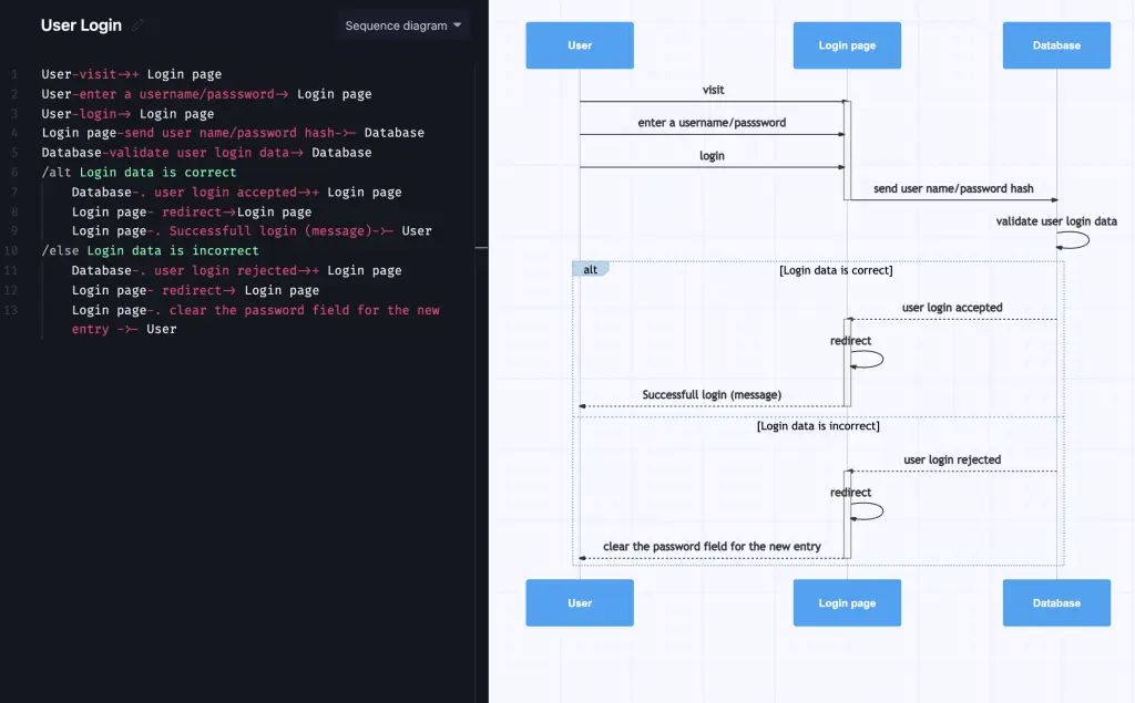
Sequence diagrams are concerned with how the different elements in a system interact and operate over time. Time in a sequence diagram progresses as you descend from top to bottom, with the objects involved appearing from left to right as they take part in the interactions being shown.
Sequence diagrams are used to track the exchange of messages and activity between the objects in the system. Developers can use sequence diagrams to document how a future system should behave, or to document how existing systems operate. They are effective at taking use cases and developing them into a more formal representation of how they should operate. Sequence diagrams can also be used in business to communicate how business objects interact and how the flow of control shifts under different conditions. Read more on UML's role in business analysis.
Make your own UML sequence diagram with Gleek.
Example of a sequence diagram
If you would like to fully understand how to create a sequence diagram in Gleek, you can follow our step-by-step guide to creating your own sequence diagram of a user login system.
Check out tutorials on online shopping and ATM withdrawal examples.
When should you use an object diagram?
An object diagram is like a snapshot of a system at a particular point in time. Object diagrams are useful for capturing how the system behaves when in operation and how the elements involved will interact in practice. Where a class diagram shows the ideal representation of the system, an object diagram represents actual instances of classes. An advantage of object diagrams is that they show real data associated with objects, so they can provide a more accurate and realistic understanding of the system.
Object diagrams are useful for both forward and reverse engineering any system. They can also be used in any business to explore and analyze real-world behavior and how the various parts of a system will interact under particular conditions.
Read also: UML vs. ER diagrams: A detailed comparison
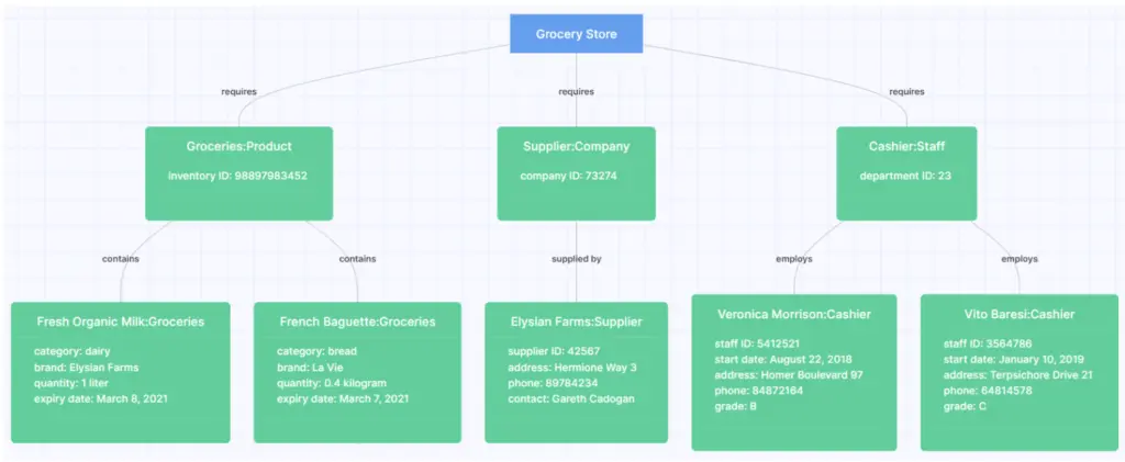
Example of an object diagram
In the object diagram representing a grocery store, a particular instance of a product can be more concretely represented as: category: dairy; brand: Elysian Farms; name: Fresh Organic Milk; quantity: 1 liter; expiry date: March 8, 2021.
Related posts
UML class diagram arrow types: explanations and examples
UML relationships explained: Dependency, Realization, Association
Sequence diagram for library management system
Mastering inheritance in class diagrams
UML Essentials: Aggregation vs Composition Explained
What is multiplicity in a class diagram?
Restaurant management system class diagram from scratch
UML vs. ER diagrams: A detailed comparison
Hospital management system class diagram using Gleek App
What an association relationship is in UML?