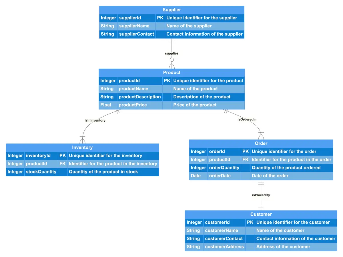
This ER diagram illustrates a Product Management System, encompassing entities such as Product, Inventory, Supplier, Order, and Customer. Each Product has unique identifiers along with attributes like name, description, and price. The Inventory entity tracks the stock quantity of each product, linking back to the Product entity. Suppliers are identified uniquely and include details like name and contact information, indicating which products they supply. Orders are associated with specific products and include details like quantity and order date. Each Order is placed by a Customer, who is uniquely identified and has attributes for name, contact information, and address. The relationships among these entities demonstrate how products are managed from inventory to orders and supplier interactions.

Edit this diagram in Gleek
Product management system diagram code in Gleek
Product
Integer productId PK "Unique identifier for the product"
String productName "Name of the product"
String productDescription "Description of the product"
Float productPrice "Price of the product"
Inventory
Integer inventoryId PK "Unique identifier for the inventory"
Integer productId FK "Identifier for the product in the inventory"
Integer stockQuantity "Quantity of the product in stock"
Supplier
Integer supplierId PK "Unique identifier for the supplier"
String supplierName "Name of the supplier"
String supplierContact "Contact information of the supplier"
Order
Integer orderId PK "Unique identifier for the order"
Integer productId FK "Identifier for the product in the order"
Integer orderQuantity "Quantity of the product ordered"
Date orderDate "Date of the order"
Customer
Integer customerId PK "Unique identifier for the customer"
String customerName "Name of the customer"
String customerContact "Contact information of the customer"
String customerAddress "Address of the customer"
Product {1}-isInInventory-{1..n} Inventory
Product {1}-isOrderedIn-{1..n} Order
Supplier {1}-supplies-{0..n} Product
Order {1}-isPlacedBy-{1} Customer
About ER diagrams
We often make an entity-relationship (ER) diagram, ERD, or entity-relationship model, in the early stages of designing a database. An ERD is perfect for quickly sketching out the elements needed in the system. The ERD explains how the elements interact. ER diagrams can be shared with colleagues. Their simplicity makes them ideal even for non-technical stakeholders.
Similar ER diagram examples
Online store entity-relationship diagram
Employee management system entity-relationship diagram
Social media platform entity-relationship diagram
Daily expense tracker entity-relationship